


| FAQ |
| Members List |
| Social Groups |
| Calendar |
| Search |
| Today's Posts |
|
#1
 05-27-2012, 07:16 PM
|
||||
|
||||
|
The new M22 I bought has the speedo cable entering (or exiting) the passenger side of the transmission tailcone. How is this cable routed? Chevelles seem to have another hole popped in the firewall...
|
|
#2
05-28-2012, 06:12 PM
|
||||
|
||||
|
I think they all came from the passenger side, except for 64; Just my 2 cents, but whatever works.
__________________
1964 GTO Auto 1970 GTO Ram Air III 4-speed 1972 Lemans Convert with endura option, 455, 4-speed |
|
#3
05-29-2012, 01:48 PM
|
||||
|
||||
|
There is a bracket spotwelded on the pass side floorboard for a clip. Not sure about another-maybe bellhousing area. Also a jumper cable for the added length. I'm doing a manual swap also and thats the way I'm going. If you look at Loffens 71 Lemans thread, the bracket on the floorboard can be seen, page 24 I think. John
|
|
#4
05-29-2012, 04:02 PM
|
||||
|
||||
|
You can see it on the bottom of this picture, but it is on the drivers side
 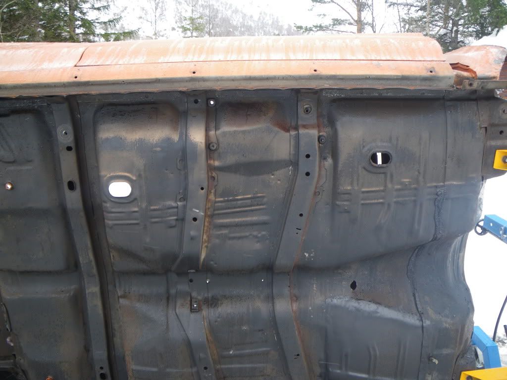 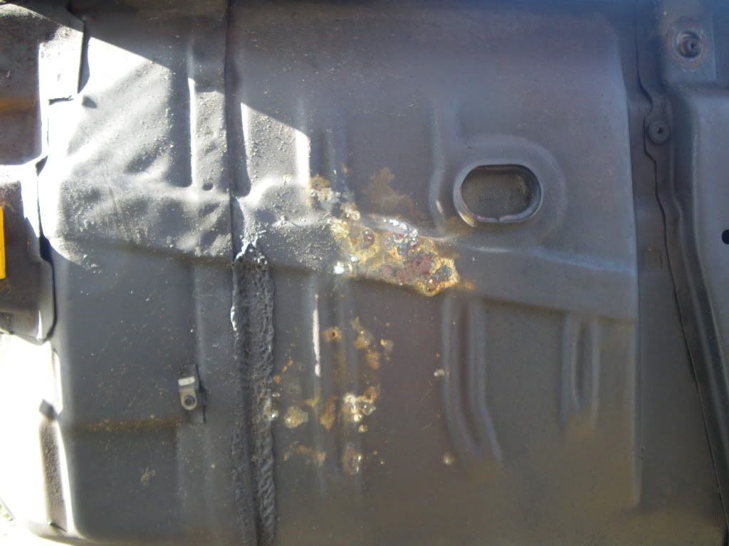
Last edited by Loffen; 05-29-2012 at 04:08 PM. |
|
#5
05-29-2012, 04:45 PM
|
||||
|
||||
|
thanks, loffen - I have almost the exact same car as yours except blue...
|
|
#6
05-30-2012, 12:18 PM
|
||||
|
||||
|
I could have sworn there was one on the pass side, thanks for the correction. I seen the other thread, great info. John.
|
|
#7
06-01-2012, 09:59 AM
|
||||
|
||||
|
Look like the last picture has been reversed/mirrord ??? Do really not know what happend to it.. sorry about that one, but it is on the drivers side

|
|
#8
12-30-2012, 08:53 PM
|
|||
|
|||
|
Guys, jumping in on this thread with some pics and comments. I'm working on the routing the speedo cable through the back drive linkage...my 71 GTO restro project. A couple of pics are attached showing how I've routed the cable from the passenger side of the tail shaft, up over the top of the bell housing and then through the keeper I've attached to keep the cable out of the linkage. I see Loffen's pics in this thread but I'm uncertain whether there's supposed to be a bracket on the floor board for a factory Hurst 4spd setup. I'd also like to get some comments in general on whether you guys think this routing is correct. thanks. Steve
|
|
#9
12-30-2012, 09:38 PM
|
||||
|
||||
|
Steve, I just checked my original 72, and that is the way mine is routed, with the exception of the cable going into that keeper bracket on the drivers side, just before it goes into the body. I dont see that keeper bracket at all on my car. Mine goes in front of the reverse lock out linkage, and in this area, there is extra padding on the cable as it comes over the top of the Trans.
__________________
Pat Brown Last edited by PB; 12-30-2012 at 09:50 PM. |
|
#10
12-30-2012, 11:52 PM
|
|||
|
|||
|
Pat, thanks for the confirmation. Mine used to be routed like yours but that was before I picked up that little bracket at Ames. I'll have to add some padding as well near the exh manifold.
|
|
#11
12-31-2012, 01:34 AM
|
||||
|
||||
|
Quote:
__________________
Pat Brown |
|
#12
12-31-2012, 01:49 AM
|
||||
|
||||
|
I cheated and went under the trans using a fabbed bracket on the trans to bellhousing bolts - straighter shot than over the trans.
|
|
#13
12-31-2012, 04:52 PM
|
||||
|
||||
|
My Survivor 72 GTO has the standard Muncie 3-speed w/ Hurst floor shift. This trans also has the passenger side speedo cable, but mine is routed under the trans. There's cable support clips on both of the lower trans to bellhousing bolts. I'm not doubting any of the members on this post, but drawing 483612 of the 1971 Assembly Manual shows both HD 3-spd & 4-spd going under the trans.
Since we're all looking for as much accurate history on our cars as we can obtain let me add this. I'm sure most of you know that the 4-speeds had a built in "Transmission Controlled Spark Switch" to operate the "Vacuum Advance Solenoid" and control vacuum to the distributor. The Muncie HD 3-speeds didn't have that, instead they used a 2 piece speedo cable with a speed sensing device (SCS speed controlled spark) between the 2 cables. When 38 MPH speed was reached the distributor vacuum advance would kick in. As I mention in the Auto-biography of my 72 GTO the short lower cable by the trans would break every 10,000 miles. After it broke twice I bought a 1 piece cable for a 70 GTO and eliminated that problem. I've attached a picture of the underside of my car that shows the cable routing. I don't know how to post the large photos, maybe I could send my picture to one of you and make it easier to view.
__________________
Bill Nawrot (Wino Bill) 1972 GTO Hdtp One Owner, GTOAA "Concours Best Original" 2007, 2013, and 2019 Auto-Biography http://oneownercollectorcar.com/inde...to-bill-nawrot HPP Sept. 2014 https://www.hotrod.com/articles/1972...-gee-no-g-t-o/ YouTube MCACN 2014 http://youtu.be/1IPQVPevbxU 1967 GTO Conv |
|
#14
12-31-2012, 05:35 PM
|
||||
|
||||
|
YNOBIL, thanks for the info.
Here's how to do the large pic thing: 1. add you pic as you did 2. preview post, open pic 3. right click, then select "copy image url" 4. go back to the text body of you post, type "[img]" then paste the URL and then type "[/img]" |
|
#15
12-31-2012, 05:49 PM
|
||||
|
||||
|
Quote:
__________________
Bill Nawrot (Wino Bill) 1972 GTO Hdtp One Owner, GTOAA "Concours Best Original" 2007, 2013, and 2019 Auto-Biography http://oneownercollectorcar.com/inde...to-bill-nawrot HPP Sept. 2014 https://www.hotrod.com/articles/1972...-gee-no-g-t-o/ YouTube MCACN 2014 http://youtu.be/1IPQVPevbxU 1967 GTO Conv |
|
#16
01-01-2013, 04:55 PM
|
|||
|
|||
|
Thanks for the page reference in the assembly guide YNOBIL! I had overlooked this. I've got a copy as well. Of course, the page is pretty rough; it's hard to make out any of the small type. But, I've attached it here for everyone to look at. Here are my conclusions:
1. The speedo cable was routed *over* the tranny tail shaft on all 4spds and some 3 spds. On other 3spds and auto's the cable looks like it was indeed routed under the tail shaft...this again is based on my interpretation of a rough diagram after looking at the writing with a magnifying glass. I highlighted the route of the 4 spd cable in yellow. 2. I believe that my setup (prior pics) is correct with respect to the route of the cable through the back lock linkage using the speedo cable bracket I purchased from Ames (part number R158NM if anyone's interested). 3. Diagram "D" in the attached pic shows the floorboard bracket in Loffen's pic...looks to be on the driver's side to the rear of the back lock linkage, per the diagram. Let me know if you agree. Steve |
|
#17
01-01-2013, 07:35 PM
|
||||
|
||||
|
Quote:
__________________
Bill Nawrot (Wino Bill) 1972 GTO Hdtp One Owner, GTOAA "Concours Best Original" 2007, 2013, and 2019 Auto-Biography http://oneownercollectorcar.com/inde...to-bill-nawrot HPP Sept. 2014 https://www.hotrod.com/articles/1972...-gee-no-g-t-o/ YouTube MCACN 2014 http://youtu.be/1IPQVPevbxU 1967 GTO Conv Last edited by YNOBIL; 01-01-2013 at 07:46 PM. Reason: Added 1972 supplement |
|
#18
01-19-2013, 09:54 PM
|
|||
|
|||
|
I am the original owner of a '72 GTO 455 HO. I am in the process of trying to resore everything that I 'messed' with over the years.
If it helps, the speedometer cable housing on my car passes under the bottom of the transmission and loops around to the drive coupling. The are two spring steel clips fastened under the two large bottom mounting bolts that mount the transmission to the bell housing, and the cable housing is held in place by these clips. I would post a picture, but much of my car is in the 'exploded' view condition right now. |
|
#19
01-20-2013, 12:57 AM
|
||||
|
||||
|
Quote:
__________________
Bill Nawrot (Wino Bill) 1972 GTO Hdtp One Owner, GTOAA "Concours Best Original" 2007, 2013, and 2019 Auto-Biography http://oneownercollectorcar.com/inde...to-bill-nawrot HPP Sept. 2014 https://www.hotrod.com/articles/1972...-gee-no-g-t-o/ YouTube MCACN 2014 http://youtu.be/1IPQVPevbxU 1967 GTO Conv |
|
#20
01-20-2013, 01:25 AM
|
||||
|
||||
|
Quote:
__________________
Bill Nawrot (Wino Bill) 1972 GTO Hdtp One Owner, GTOAA "Concours Best Original" 2007, 2013, and 2019 Auto-Biography http://oneownercollectorcar.com/inde...to-bill-nawrot HPP Sept. 2014 https://www.hotrod.com/articles/1972...-gee-no-g-t-o/ YouTube MCACN 2014 http://youtu.be/1IPQVPevbxU 1967 GTO Conv |
| Reply |
|
|
The PY Online Forums is the largest online gathering of Pontiac enthusiasts anywhere in the world. Founded in 1991, it was also the first online forum for people to gather and talk about their Pontiacs. Since then, it has become the mecca of Pontiac technical data and knowledge that no other place can surpass.


 Linear Mode

