


| FAQ |
| Members List |
| Social Groups |
| Calendar |
| Search |
| Today's Posts |
|
#61
 04-04-2022, 03:23 PM
|
|||
|
|||
|
he's talking about DI not having constant fuel spray to keep the back of the valves clean. Catch cans are cheap and easy and make sure the PCV system doesnt suck in excess oil vapor that will gum up the back of the valves over time.
|
| The Following User Says Thank You to 62posbonny For This Useful Post: | ||
|
#62
04-04-2022, 07:18 PM
|
||||
|
||||
|
Quote:
|
|
#63
04-06-2022, 12:48 AM
|
||||
|
||||
|
I will research the oil vapor issue more and see if it warrants attention.
Had some time today to address the clutch and master cylinder. I was originally going to mount the clutch master with a brace under the master cylinder but decided to build this: It mounts inside the firewall and holds the clutch master. It also seals off the engine compartment better. It is a bit to fish thru the firewall. It also ended up being a bit off center but won't affect anything. Were I to make more I would build a fixture to make them dead square. These two sets of holes define the brake stop switch mount. The uppers are for manual - lower does power brakes. Note also the pedal height dimension - useful data the shop manual has! Last edited by Scarebird; 04-06-2022 at 12:56 AM. |
| The Following User Says Thank You to Scarebird For This Useful Post: | ||
|
#64
04-06-2022, 05:46 AM
|
||||
|
||||
|
That is cool!
|
|
#65
04-15-2022, 06:46 PM
|
||||
|
||||
|
Quote:
|
|
#66
04-15-2022, 07:37 PM
|
|||
|
|||
|
Quote:
|
|
#67
04-15-2022, 10:48 PM
|
||||
|
||||
|
This is the first prototype bracket. The next version will lower the pump 3/4" for better radiator hose clearance.
This is the initial setup. The pump is 1998-02 F but will take the 1997-05 Corvette unit also. The tensioner and idler are GM parts. The LT motors do not have them - I wonder if the alternator simply pivots and is used to tension the belt - kind of an overcenter thing? I will try it with the newer version once it is cut. |
|
#68
04-16-2022, 03:37 PM
|
|||
|
|||
|
That's a slick and uncomplicated accessory system for the power steering pump addition. Thank you for the pictures and the explanation.
I also have a long block, like what you originally had (mine is an L87, 6.2L engine). I'm not sure how the belt tensioning would be accomplished without a tensioner somewhere in the system. The alternators appear to be fixed mounted (not capable of swiveling) on the factory-stock systems that I've looked at. I'll also have an AC compressor in my installation along with the addition of a power steering pump. Thanks again for showing us your solution. |
|
#69
04-16-2022, 04:06 PM
|
||||
|
||||
|
MY guess is the left bolt is removed after the right is loosened - allowing the alternator to pivot towards the throttle body.
|
|
#70
04-17-2022, 07:23 PM
|
||||
|
||||
|
This was really bugging me, so I pulled it out, broke a weld on one side and bent it to be straight and rewelded.
The piece was straight, firewall must be at an angle there. |
|
#71
05-27-2022, 11:39 PM
|
||||
|
||||
|
Work has been insane lately trying to keep up. Today I had a bit of time so decided to pop the motor in with the harness loose and then decide where what needs to go. The harness and programmed ECU was supplied by SwapTime out of Las Vegas.
As you see it is quite roomy in the back - the trans/engine split line is as stock. The mounts work superbly - went right in as designed. I cannot attach the file here, but anyone who wishes them I will send to, then you can have them cut. |
|
#72
05-28-2022, 11:42 PM
|
||||
|
||||
|
More time today. I decided to stab in the trans to check fitment and gear up to fab the crossmember mounts. One thing that always bugged me was transmissions are never flat on the bottom - always rolling about. I flipped the TKX on it's top and took a hard look. I noted that 2 of the lower bolts could be made to hold a "base" so to speak, so a few minutes of fab work and this is what I got:
Sits on some stacked milk crates atop a rolly cart just fine - quite stable. I ran the vehicle lift all the way up,then laid the trans on it and rolled it under the car - then lowered the car. Slid in perfectly - hopefully she is just as trampy when the clutch and other components are in place. I was able to reuse the stock trans support and mounts - fit in perfectly, The rear mount will need a 1/2 - 3/4" shim to get to the proper driveline angle and one corner of the shifter porch will need a quick visit from the singlejack to clear the shifter mount. All in all not a bad day, though the shifter shows signs of being a real bugger. Hurst makes a shifter called the Sidewinder that would have solved this but requires machining to the tailhousing to work. 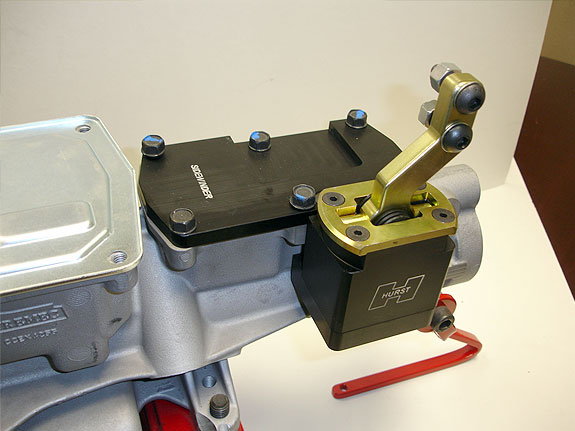 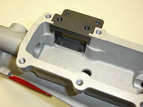 Last edited by Scarebird; 05-28-2022 at 11:49 PM. |
|
#73
06-12-2022, 11:24 PM
|
||||
|
||||
|
Time to fit a driveshaft.
I raised the car as high as it will go on the lift, then put an exhaust stand under the differential and lowered the car till the lift engaged the locks. I then used the screw feature on the stand to raise the rear till the frame barely came off the rear lift arms. My lift is also firmly tied into the roof structure so no danger of the lift pulling out of the concrete. I measured the centerline of the bearing cap surfaces and subtracted an inch for install then cut my existing driveshaft in the lathe with a parting tool. I then mounted the section with the yoke intending to carefully whittle away the tube and reuse the yoke. Wrong. The section was not held firm enough and popped out when I got greedy with the cut depth. It hit the tool post and scratched the yoke in the thinnest section. Dammit. Luckily one of the local driveshaft shops had a yoke for a fair price ($40) I needed to trim the insert section of it about 0.016" to get a slight interference fit. This time I mounted it first in the lathe, drilled a centering hole and used that to retain the yoke. Uneventful this time. Most shops use a MIG gun to weld up the yokes, I elected to Heliarc it for good penetration and low bead. Fitted up to the car revealed good results - good engagement length and removal ease. Last edited by Scarebird; 06-12-2022 at 11:42 PM. |
|
#74
06-12-2022, 11:40 PM
|
||||
|
||||
|
Now that was finished, time to check the driveline angles.
I made a big protractor from a AutoCAD drawn file (available to who wants a copy), printed it out and spray glued it to a piece of foamboard - carefully cutting out the right angle edges. A piece of 0.063 welding rod made a nice pointer. With the rear suspension at ride height I got the following data: Engine / shaft angle: 2° Shaft / Diff angle: 5° It looks like I will need to drop the tail of the trans 1.5° to split the difference. Not an issue as the shifter mounting plate is almost touching the floor pan. One thing that does bother me is the engine and diff are not parallel at all: 5° difference. I will need to see if this is an issue. |
|
#75
06-13-2022, 08:58 AM
|
|||
|
|||
|
Quote:
|
|
#76
06-13-2022, 12:14 PM
|
||||
|
||||
|
no, the drivetrain is dead in line horizontally. This is vertical alignment.
|
|
#77
06-13-2022, 04:00 PM
|
|||
|
|||
|
Quote:
|
|
#78
06-17-2022, 11:26 PM
|
||||
|
||||
|
I noted that the airbox in my 2016 GMC may fit well in the passenger side battery area. Not so much...
|
|
#79
08-19-2022, 12:32 AM
|
||||
|
||||
|
Work has been a bugger the last 2 months. Little time to work on the 71 other than pecks and paws.
Last month worked on sorting out the wiring harness while the engine is out. Swap Time did a decent job but definitely room for improvement. Note once again this motor is a pretty new architecture that is kinda slow to catch on as far as I can see. I cleaned up the wiring a bit, made a bracket to retain the harness under the front of the oil pan. The drawings are available for the asking. The OEM 2014-19 harness guide does not match the 2020 motor so it was trimmed back to fit better. I also will incorporate a couple extra wires in the harness for stuff like oil sender feed as I am running steam gauges currently. |
|
#80
08-19-2022, 12:38 AM
|
||||
|
||||
|
Time to clean up the driver's inner fender. While practical I did not like the kluge the headlight relays and busses presented. The battery is now in the trunk so this stuff will go behind the LH head light core support area.
Other extraneous wiring will go away too. |
| Reply |
|
|
The PY Online Forums is the largest online gathering of Pontiac enthusiasts anywhere in the world. Founded in 1991, it was also the first online forum for people to gather and talk about their Pontiacs. Since then, it has become the mecca of Pontiac technical data and knowledge that no other place can surpass.


 Linear Mode

