We are now going to fast-forward to the to the assembly stage of the project.
Before we do, I'll describe the work that went on in the machine shop. First, I completed the disassembly of the motor and brought the pieces to the machine shop for cleaning. The block, crank, and rods were baked, blasted, and jet washed. After the block was completely clean it was maganfluxed to make sure there were no cracks. The block was then was align honed, decked, and bored 0.030 over. The machine shop installed the cam bearings, block plugs, and oil passage plugs.
After the crank was cleaned, all it took was a polishing to make it serviceable.
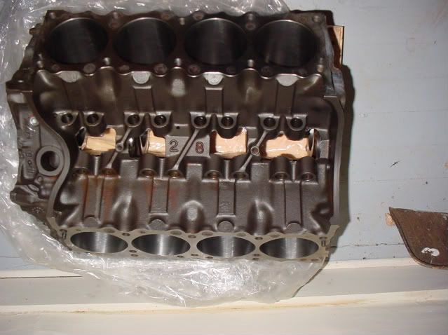
Here's how the block looked after it came out of the machine shop.
Tip for Pontiac builders: pay close attention to the machine work where the rear main seal fits. If this is not accurate, your chances of a leaky rear main just increased.
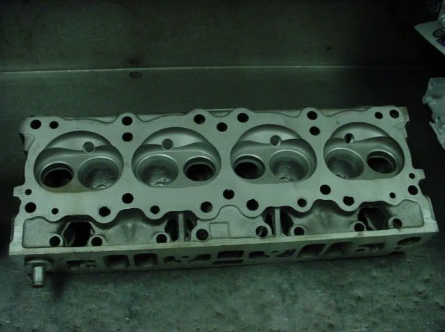
If you noticed I didnt talk much about the original heads, it's because I decided not to use them. The stock 46 heads made too much compression for the street motor that I wanted to build, so my machinist recommended a set of 6X (4) heads. The heads were decked, new valve guides were installed, and given a competition valve job. I let the machine shop assemble the heads.
Since this was not a rush rebuild, the disassembly of the motor occur in the fall of 2008 and all the machine work occurred during following winter. During the spring and early summer of 2009, I cleaned all the other parts and bought whatever pieces that were needed, such as an oil pump.
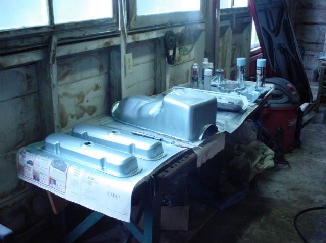
After all the parts are completely clean and dry, it is time to paint. In this photo you can see the valve covers, oil pan, valley pan, timing cover, and water pump. Many light coats will work better than one drippy one.
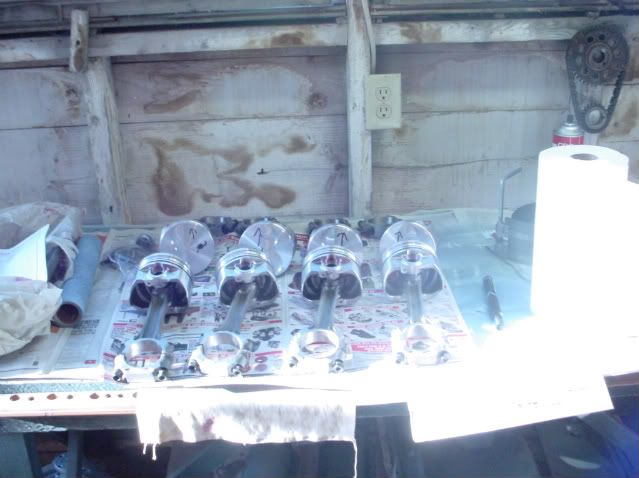
Here is a shot of the pistons hung on the rods. We let the machine shop do this work since they had the tools, and we didn't
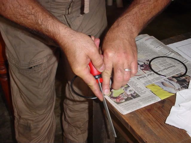
We begin the rebuilding process by file fitting the rings.
If you've not built a motor before, it's a good idea to call on a friend who has. This is my friend Karl filing a ring (Karl is sort of like Waylon Jennings on the Dukes of Hazzard, you are only going to see is his hands not his face.) Karl is filing from the outside to the inside of the ring. This is so that there'll be no burr to catch on the cylinder. If you do create a burr, remove it with a fine stone.
As you file the rings, you will need to stop frequently and check the ends of the ring for squareness. The best way to do this is to hold the ring up to the light, which is what I am doing in this picture.
You'll also need to check your progress by installing the ring into a cylinder. Make sure the ring is square in the bore. Once installed, you can check the ring gap with a feeler gauge. Since I'm the one building the motor, we took the time to file fit all of the rings, cylinder by cylinder, to the exact specification called for by the ring manufacturer.
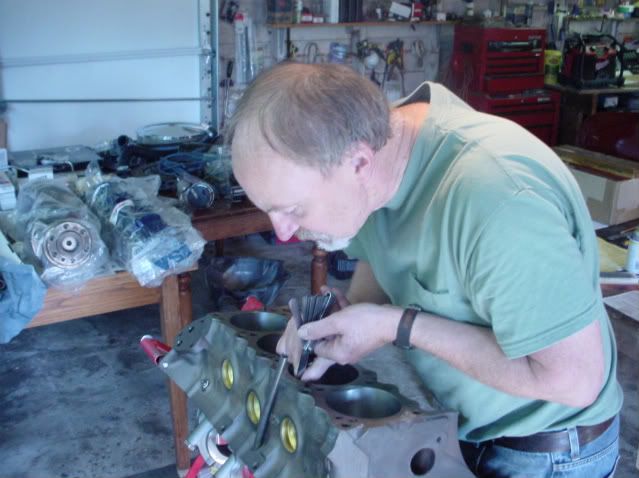
Now, we're going to do some more measuring. In this case were going to measure the clearance between the main bearings and the crank journals. This can be checked in several ways. If you happen to have a set of machinist gages, you could measure the ID of the bearing shell and that of the OD of the journal and calculate your clearance.
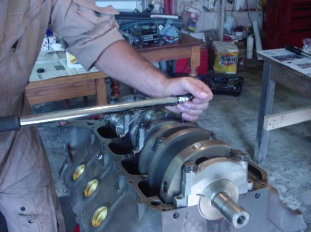
The second, and more common way for amateur builders, is to use plasti-gage. To do this test, you need to install the bearing in the block. Lay the crank on the bearing halves. Next, you will need to place pieces of plasti-gage on each of the main bearing journals. With the plasti-gage in place, you then install the main bearing caps with bearing shells and torque them to specification (120 foot-pounds for the rear main, and 100 foot-pounds for the others) for a Pontiac 428.
Make sure to immobilize the crank during this process, because if it moves it will spoil the reading. (You can see where we used a magic marker to make sure the crank didn't move relative to the main cap.)
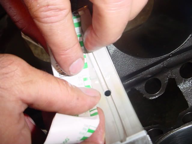
Once the mains are torqued to spec, loosen them up and remove the bearing shell. You will see that the plasti-gage has been squished. The tighter the clearance, the more squished the plasti-gage will be. The squished plasti-gage is then compared to the chart on the plasti-gage wrapper, which allows you to determine your clearance. Since this was my motor, we took the time to check all of the journals, not just one.
This is another fast forward in the rebuilding procedure. I am skipping a very important part which is the temporary installation of the piston/rod assembliess on the crank for the purpose of checking rod bearing clearance. Plasti-gage can be used to check clearance for the rod bearings just as it's used for the main bearings. Some people will check only one bearing and call it good. We did them all just for my peace of mind.